4-20 mA Transmitter Wiring: Understanding 2-Wire, 3-Wire, and 4-Wire Systems
Brian Craig
July 30, 2025
In the world of industrial automation, precise and reliable signal transmission is paramount. At The Transmitter Shop, we understand that selecting the right transmitter wiring type for your instruments, whether it's a 4-20 mA temperature sensor, a 4-20 mA pressure transducer, or a differential pressure transmitter 4-20 mA is crucial for system performance and longevity.
The 4-20 mA current loop has long been the industry standard for analog signal transmission, prized for its robustness against electrical noise and its inherent ability to detect broken wires (a 0 mA reading indicates a fault). But did you know that not all 4-20 mA transmitters are wired the same way? Understanding the differences between 2-wire, 3-wire and 4-wire systems is key to successful installation, maintenance and troubleshooting.
This comprehensive guide will demystify these wiring types, helping you make informed decisions for your applications, from a simple temperature transmitter 4-20 mA to complex process controls.
Why 4-20 mA Remains the Standard
Before diving into wiring, let's briefly revisit why the 4-20 mA current loop is so prevalent:
Noise Immunity: Current signals are less susceptible to voltage drops and electromagnetic interference (EMI) over long distances compared to voltage signals.
Live Zero: The 4 mA "live zero" allows for differentiation between a true zero measurement and a broken wire or power loss (which would result in 0 mA).
Intrinsic Safety: Many 4-20 mA systems can be designed for intrinsic safety in hazardous environments, limiting the energy available to cause ignition.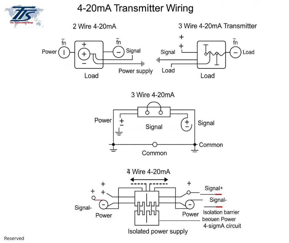
Now, let's explore the different wiring configurations.
1. The 2-Wire 4-20 mA Transmitter
The 2-wire configuration is arguably the most common and often the simplest to implement.
How it Works:
A 2-wire 4-20 mA transmitter uses just two wires for both power supply and signal transmission. The transmitter acts as a variable resistor within the current loop. The power supply (often from a PLC, DCS input card, or a dedicated power supply) provides the voltage and the transmitter modulates the current flowing through these two wires between 4 mA (representing the low end of the measurement range) and 20 mA (representing the high end). The instrument essentially "steals" a small amount of power from the loop to operate.
Key Features:
- Power and signal share the same two conductors.
- The device draws its operating power directly from the 4-20 mA loop.
- Fewer wires mean reduced cabling and installation costs.
- Simplicity makes it excellent for field devices.
Common Applications:
- 4-20 mA pressure transducer
- 4-20 mA temperature sensor
- Level transmitters
- Simple flow sensors
2. The 3-Wire 4-20 mA Transmitter
The 3-wire system offers more flexibility, particularly when the transmitter requires more power than a 2-wire system can efficiently provide.
How it Works:
A 3-wire 4-20 mA transmitter utilizes two wires for its independent power supply (e.g., +24V DC and GND) and a third separate wire for the 4-20 mA signal output. This means the transmitter has a dedicated power source that does not interfere with the signal transmission itself. The signal current is typically referenced to the transmitter's power supply common.
Key Features:
- Dedicated power supply for the transmitter's internal electronics.
- The 4-20 mA signal travels on its own wire.
- Can support larger displays, integrated diagnostic functions, or more complex processing.
- The signal line is less impacted by voltage drops due to power consumption.
Common Applications:
- Temperature humidity transmitter 4-20 mA
- Transmitters with large local displays or keypads
- Devices requiring significant internal processing power
- Some wireless 4-20 mA transmitter gateways (though the wireless module itself might be 2-wire powered from the sensor)
3. The 4-Wire 4-20 mA Transmitter
The 4-wire configuration provides the highest degree of isolation and is typically used for instruments that require substantial power or offer highly precise, isolated outputs.
How it Works:
A 4-wire 4-20 mA transmitter employs two wires for its power supply (which can be AC or DC) and two completely separate wires for the 4-20 mA signal output. This complete separation ensures maximum isolation between the power source and the signal loop, virtually eliminating issues like ground loops and noise interference.
Key Features:
- Power and signal circuits are entirely separate.
- Can power complex internal components, heaters, or analytical functions.
- Excellent for environments with high electrical noise.
- Requires the most cabling.
Common Applications:
- Analytical instruments (e.g., pH, conductivity, gas analyzers)
- Some advanced flow meters (e.g., magnetic flow meters)
- High-precision pressure transmitter 4-20 mA with advanced diagnostics
- Devices needing internal heaters or refrigeration.
- Differentiation at a Glance: 2-Wire, 3-Wire and 4-Wire Transmitters
Here's A Comparison Table to Summarize the Key Differences:
|
Feature |
2-Wire Transmitter |
3-Wire Transmitter |
4-Wire Transmitter |
|
Wiring |
2 wires (Power & Signal) |
3 wires (2 for Power, 1 for Signal) |
4 wires (2 for Power, 2 for Signal) |
|
Power Source |
Draws power from the 4-20 mA loop |
Independent external power supply |
Independent external power supply |
|
Signal Isolation |
None (shared wires) |
Partial (signal separate from power return) |
Complete (power and signal fully isolated) |
|
Power Availability |
Limited (must operate within loop current) |
Moderate (more than 2-wire) |
High (can power complex electronics) |
|
Noise Immunity |
Good (as current loop) |
Better (separate signal path) |
Excellent (full isolation) |
|
Cost/Complexity |
Lowest |
Medium |
Highest |
|
Typical Use Cases |
Pressure, Temperature, Level |
Humidity, Displays, Advanced Diagnostics |
Analytical, High Power Needs, Ultimate Isolation |
|
Advantages |
- Simplicity of wiring - Reduced cabling/installation cost - Inherently safer (lower power) |
- More power for features (displays, HART) - Less susceptible to signal voltage drops - Easier to troubleshoot signal path |
- Superior noise immunity - High power capacity for complex devices - Eliminates ground loop issues |
|
Disadvantages |
- Limited power for internal electronics - Susceptible to voltage drops on long runs - Power supply must be robust |
- More wiring than 2-wire - Potential for ground loops if not wired correctly |
- Most complex and expensive wiring - Requires more space in conduits/panels |
Choosing the Right 4-20 mA Transmitter Wiring Type
Selecting the appropriate 4-20 mA current loop transmitter configuration depends on several factors specific to your application:
- Does the sensor need a local display, heating elements, or advanced processing? If so, 3-wire or 4-wire might be necessary.
- For long distances, 2-wire can be cost-effective due to less cabling, but consider voltage drops.
- In electrically noisy environments, the superior isolation of a 4-wire system can prevent signal corruption.
- While 2-wire systems often simplify intrinsic safety compliance, specialized barriers are available for all types.
- Basic measurement often suits 2-wire, while more complex functions might demand 3-wire or 4-wire.
Your Partner in Industrial Measurement
Understanding the nuances of 4-20 mA transmitter wiring is fundamental for any industrial process. Whether you're integrating a new 4-20 mA temperature sensor or troubleshooting an existing pressure transmitter 4-20 mA, knowing the difference between 2-wire, 3-wire and 4-wire systems empowers you to design and maintain more reliable and efficient automation systems.
At The Transmitter Shop, we pride ourselves on offering a wide range of high-quality 4-20 mA transmitters and providing the expertise to help you choose the perfect solution for your specific needs. From selection to transmitter wiring guidance, we are your trusted partner in precision measurement.
Related Posts
- What are the Steps Involved in Calibrating Pressure Gauge?
- All Important Questions on Reconditioned Transmitters Answered
- Is Remanufactured Transmitter a Better Option than a New One?
- Differential Pressure Transmitters: How Do They Help in Flow Measurements?
- 3 Whats that Explain How Often You Should Calibrate Pressure Transducer
- Guidelines for Troubleshooting Pressure Transducers
- Learn How to Calibrate a Pressure Transmitter – II
- Learn How to Calibrate a Pressure Transmitter
- Know Three Interesting Uses of Pressure Transmitters
- Things to Check before Buying a New Pressure Transmitter
- A Look at Various Types of Industrial Transmitters – Part II
- A Look at Various Types of Industrial Transmitters Part I
- All Questions on Smart Transmitters and their Calibration Answered
- 3 Major Pressure Transmitter Technologies That Made the Device Popular
- An Unconventional Guide to Selecting the Right Pressure Sensor
- Factors To Be Considered While Differentiating $40 and $400 Pressure Transmitters
- Tips to Augment the Performance and Service Life of Pressure Transmitter
- Factors of Consideration When Choosing Pressure Transmitters
- 5 Most Popular Pressure Transmitter Technologies
- Tips to Improve the Performance of Pressure Sensors
- Factors to Consider When Choosing a Pressure Transmitter Manifold
- Safety Tips for Differential Pressure Transmitter Operation
- Impact of Shock and Vibration on Pressure Transducer
- Rosemount 3051S vs 3051C Transmitter – What is Your Choice?
- Rosemount 2088 Vs Rosemount 3051 – A Few Points of Differences Discussed
- Difference in Conventional Transmitters and Smart Transmitters
- How to Choose Diaphragm Seals for Your Application?
- How to Select Pressure Transmitter for Your Application?
- Remote Seals: Significance, Working Principle & Applications
- How Do You Calibrate A Flow Transmitter?
- What is Absolute Pressure Transmitter & how does it work?
- HART Communication Protocol: Overview, Working Principle, Benefits in Industrial Automation
- Absolute and Gauge Pressure Transmitters - Overview and Working Principle
- Flow Meter vs Flow Transmitter: Know the Difference
- How Do You Test for 4 to 20mA Signal in a Pressure Transmitter?
- Multivariable Transmitter: What Is It and How Does It Work?
- Pressure Transmitters vs. Pressure Transducers: Learn the Differential Characteristics
- Procedure to Calculate Accuracy of Pressure Transmitter Discussed
- Testing Pressure Gauges: Processes of Verification Test and Functional Test
- An Ultimate Selection Guide for Flow Transmitters
- The Benefits and Challenges of HVAC System Balancing
- Fluid Flow Isolation Techniques for Pressure Instrumentation
- Understanding Pressure Ranges and Units for Fluid System Monitoring
- Understanding the Impact of Pressure Fluctuations on Drying Performance
- Monitoring and Controlling Energy Production in Power Plants
- Common Challenges in Air Flow Measurement and How to Overcome Them
- Pressure Monitoring in Pump Systems: A Comprehensive Guide
- Exploring Density and Viscosity Measurement in Industrial Processes
- Pneumatic Pressure Controllers: A Safe Choice for Hazardous Areas
- A Practical Guide to Vacuum Measurement and Operation
- 4-20 mA Transmitter Wiring: Understanding 2-Wire, 3-Wire, and 4-Wire Systems
- Flow Measurement Challenges in Subsea Operations
- Flow Measurement Challenges in Subsea Operations
- Pressure Sensing Sensor Modes of Measurement Key Differences and Benefits
- Electromagnetic Flow Sensors for Abrasive and Corrosive Fluids
- Mass Flow Meters and Their Working Principles
- Best Explosion Proof Switches for Hazardous Environments
- Best Explosion Proof Switches for Hazardous Environments
- Furnace Flame Sensor Faults Everything You Need to Know for Safe Operation
- Pneumatic Pressure Controllers: A Safe Choice for Hazardous Areas
- A Practical Guide to Vacuum Measurement and Operation
- Understanding Electrochemical Detection: Principles, Techniques and Environmental Application
QUICK ENQUIRY
