Brian Craig
April 27, 2023
HVAC system balancing involves adjusting the airflow, temperature, and pressure in ductwork and pipes to ensure that the system is functioning efficiently and providing maximum comfort. In this blog post, we will discuss the benefits and challenges of HVAC system balancing and how pressure transmitters play a crucial role in achieving optimal balance.
HVAC system balancing is a process that helps ensure that you’re building's heating, ventilation, and air conditioning (HVAC) system is working correctly. This involves testing and adjusting the airflow and environmental conditions like temperature, humidity, and air quality of your HVAC system. During this process, professionals measure the air volume and pressure in different areas of your building and make adjustments to HVAC components such as air diffusers, grilles, dampers, and fans. This helps to achieve the desired airflow and temperature throughout the building.
These two terms are closely related but not identical, and understanding the difference helps technicians target the right corrective actions.
HVAC air balancing specifically refers to the adjustment of airflow measured in cubic feet per minute (CFM) at each supply outlet, return inlet, and exhaust point in the system. The goal is to match actual airflow to the design airflow specified on the HVAC drawings for each zone. Air balancing is performed on the air-side of the system: ductwork, dampers, diffusers, grilles, and the air handling unit (AHU) fan.
HVAC system balancing is the broader term that encompasses both air balancing and hydronic (water-side) balancing. Hydronic balancing addresses the flow of chilled water or hot water through coils, pumps, and piping. A building may need air balancing only, water balancing only, or both depending on the HVAC system type.
For most commercial and light industrial buildings with forced-air systems, when people refer to "balancing the HVAC system," they mean air balancing. This article focuses primarily on air balancing procedures, instruments, and challenges, with system balancing covered in the broader context.

A professional air balancing procedure follows a structured sequence. Skipping steps or balancing out of order is the most common cause of callbacks and re-balancing jobs.
Before touching any damper or diffuser, the technician must obtain the original HVAC design documents: the air balance schedule showing design CFM for every supply, return, and exhaust point; equipment schedules showing AHU fan curves, design static pressure, and design airflow; and duct layout drawings. Without design values, there is no target to balance to you are simply guessing at airflow distribution.
Walk the entire system before taking any measurements. Confirm all dampers are operational and not stuck open or closed. Verify all supply and return grilles are open and unobstructed. Check that AHU filters are clean a clogged filter will reduce system static pressure and make balancing results unreliable. Confirm fans are rotating in the correct direction. Note any obvious duct damage, disconnected flex duct, or missing insulation.
Before balancing individual outlets, establish the baseline total airflow at the air handling unit. Measure fan RPM using a tachometer and compare against the design fan curve. Use a pitot tube traverse or a calibrated airflow measurement station to measure total supply CFM at the AHU discharge. If total system airflow is more than 10% below design, find the cause dirty filter, undersized fan, collapsed ductwork before proceeding with outlet balancing.
Using a balancing hood (also called a capture hood or flow hood) or a rotating vane anemometer, measure the actual CFM at every supply diffuser and return grille. Record both the design CFM and the measured CFM for each outlet. Calculate the ratio: Measured CFM / Design CFM. A ratio of 0.90 to 1.10 (within ±10% of design) is generally acceptable per ASHRAE guidelines. Outlets below 0.85 or above 1.15 require adjustment.
This is the most critical and most commonly misunderstood step. Do not simply close dampers on outlets that are over-delivering and move on. Use the proportional balancing method: identify the outlet farthest from the AHU (the index circuit) and set all other branches relative to it. The index circuit damper should remain fully open; all others are throttled proportionally. This preserves system static pressure and prevents the fan from fighting against excessively closed dampers.
Every damper adjustment changes the pressure balance across the entire duct system. After adjusting any branch damper, re-measure all outlets downstream and in adjacent branches before adjusting the next damper. This iterative process is why HVAC air balancing is time-intensive there are no shortcuts that produce repeatable, stable results.
Once all outlets are within the acceptable tolerance band, record final as-left readings for every point. The completed air balance report should list design CFM, measured CFM, percent of design, and the final damper position for every supply and return. This report becomes part of the building's commissioning documentation and is required for LEED certification projects.
HVAC air balancing is the process of measuring and adjusting airflow through every supply and return register, duct branch, and zone in a building to ensure each space receives its design-specified volume of conditioned air. A properly air-balanced HVAC system eliminates hot and cold spots, reduces energy waste, and prevents excessive wear on fans, compressors, and dampers. It is typically performed during HVAC commissioning, after major renovations, or when persistent comfort complaints cannot be resolved through thermostat adjustments alone.
The balancing process involves measuring and adjusting various aspects of the HVAC system to achieve optimal performance. Common balancing techniques include air balancing and water balancing, and factors such as duct design, equipment sizing, and control system settings can all impact balancing. Proper documentation and measurement verification are also essential to ensure accuracy and consistency.
Accurate air balancing depends on calibrated instruments. Using the wrong tool or an uncalibrated instrument is the fastest way to produce a balance report that does not reflect reality.
Capture Hood (Flow Hood): The most common field tool for measuring airflow at individual supply and return registers. The hood fits over the diffuser and captures all discharged air, measuring total CFM directly. Capture hoods are accurate to ±3% when used correctly on standard diffusers but can introduce error on high-throw or high-velocity outlets.
Rotating Vane Anemometer: Measures air velocity in feet per minute (FPM). Used at grilles and diffusers where a capture hood cannot be sealed properly. Velocity readings are multiplied by the effective area of the outlet to calculate CFM. Requires knowledge of the outlet's effective area, which is typically found in manufacturer data.
Pitot Tube and Manometer: Used for measuring velocity pressure in ductwork via a traverse measurement. A pitot tube traverse is the most accurate method for measuring duct airflow and is used to verify AHU total discharge CFM. The manometer measures the difference between total pressure and static pressure to calculate velocity pressure, which converts to velocity and then to CFM.
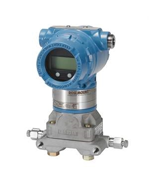
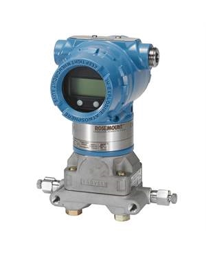
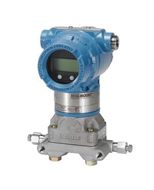
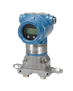
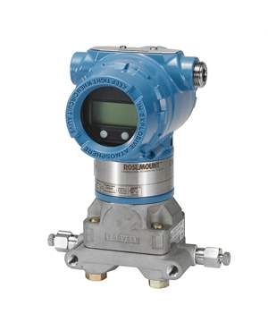
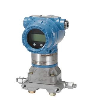
Differential Pressure Transmitter: Critical for continuous monitoring of static pressure across AHU filters, coils, and fan sections during balancing. A differential pressure transmitter connected across the filter bank immediately indicates when filter loading is affecting system performance. Rosemount differential pressure transmitters such as the 3051 series are widely used in HVAC air handling units for this purpose they provide accurate, repeatable readings that a technician can monitor in real time at the building automation system (BAS) without climbing into mechanical rooms repeatedly during balancing.
Digital Tachometer: Measures fan RPM to verify the fan is operating at design speed. A fan running below design RPM delivers below-design airflow regardless of how the dampers are set.
Inclined Manometer or Digital Micromanometer: Measures very low static pressures 0.01 to 2 inches water column common in residential and light commercial HVAC ductwork. Used to measure available static pressure at branch takeoffs and confirm the duct system has sufficient pressure to deliver design airflow to the farthest outlets.
For buildings with chilled water or hot water HVAC systems including most large commercial, hospital, and industrial facilities air balancing alone is not sufficient. The water-side of the system must also be balanced to ensure each coil receives its design water flow rate.
Hydronic balancing involves measuring differential pressure across each coil and pump circuit, then adjusting balancing valves to achieve design GPM (gallons per minute) at each terminal unit. Differential pressure transmitters play an even more central role in hydronic balancing than in air balancing they are installed permanently across pump headers, bypass lines, and critical terminal units to provide continuous differential pressure monitoring that the BAS uses to modulate control valves.
An unbalanced hydronic system will defeat even a perfectly air-balanced system. If a coil receives insufficient chilled water flow, it cannot cool the supply air to the design leaving air temperature, and the zone will be too warm regardless of how accurately airflow is set at the diffusers.
In practice, full HVAC system balancing on a large building requires a team: one group balancing the air side in parallel with another team balancing the hydronic circuits, coordinating through the BAS and the commissioning agent.
Even well-designed HVAC systems develop balance problems over time. These are the issues technicians encounter most frequently:
This is the most common complaint that triggers an air balancing investigation. Causes include dampers that have slipped from their balanced position, flex duct that has collapsed or kinked, supply diffusers that have been blocked by furniture or ceiling tiles, or occupancy changes that increased the heat load in a zone beyond the original design. Measure CFM at the problem zone's supply outlets first if airflow is at design but the zone is still uncomfortable, the issue is load, not balance.
High velocity noise at supply diffusers almost always means a damper upstream has been closed too far, creating high velocity through a reduced opening. Increasing static pressure to force airflow through a partially closed damper causes turbulence and noise. The fix is to open the problem damper and re-balance proportionally rather than simply throttling back one outlet.
If the AHU fan is operating at significantly higher static pressure than design, the duct system has excessive restriction. Common causes include a clogged filter (check first), closed or partially closed fire dampers (often forgotten after testing), improperly positioned balance dampers left over from a previous re-balance, or a duct section that has collapsed internally. A differential pressure transmitter across the AHU filter bank will identify a clogged filter immediately.
If damper adjustments don't hold the system goes out of balance quickly after each re-balance the fan is likely operating at an unstable point on its performance curve, dampers are not locking properly, or the duct system has excessive leakage that changes with system pressure. Duct leakage testing (duct blaster test) should be performed before attempting to balance a system with persistent instability.
If exhaust airflow exceeds supply airflow in a zone, the space will run at negative pressure relative to adjacent areas. This causes cold drafts through building envelope gaps in winter, pulls unconditioned air and contaminants into the space, and can affect combustion appliances. Verify exhaust fan CFM against design and compare to supply CFM for the zone. Spaces should generally run at slight positive pressure (0.02 to 0.05 inches WC) to prevent infiltration.
Pressure transmitters are not just measurement tools for HVAC balancing they are the instrumentation backbone that makes accurate, repeatable air balancing possible in modern building automation systems.
During the air balancing procedure, differential pressure transmitters installed across AHU filter sections give the technician real-time visibility into filter loading without requiring physical access to the air handler. A clean filter typically reads 0.2 to 0.5 inches water column differential pressure; a loaded filter requiring replacement reads 1.0 inches or more. Performing air balancing with a loaded filter produces results that will be invalid as soon as the filter is changed.
Static pressure transmitters installed in main duct risers allow the BAS to monitor supply duct static pressure continuously and modulate fan speed through the variable frequency drive (VFD) to maintain a setpoint typically 1.0 to 1.5 inches WC in commercial systems. This duct static pressure control strategy is the most energy-efficient method of operating a variable air volume (VAV) HVAC system and depends entirely on accurate, stable pressure transmitter readings.
For VAV systems specifically, each VAV box uses an internal differential pressure sensor to measure the velocity pressure across its inlet and calculate airflow. The accuracy of this measurement determines whether the VAV box can accurately maintain zone airflow setpoints. Poor-quality or uncalibrated VAV box sensors are one of the primary reasons air balancing results degrade over time in variable air volume systems.
Improved Energy Efficiency and Cost Savings: Balancing the HVAC system can help to optimize energy consumption, resulting in cost savings on utility bills. Pressure transmitters can help to identify areas of the system that are consuming more energy than necessary, allowing for targeted adjustments.
Better Indoor Air Quality: Balancing the HVAC system can help to reduce indoor air pollution and improve air quality by ensuring proper ventilation and air filtration. This can help to reduce the risk of respiratory issues and improve overall health.
Enhanced Comfort and Temperature Control: Balancing the HVAC system ensures that air is distributed evenly throughout the building, resulting in consistent temperature and improved comfort levels. Pressure transmitters can help to measure and adjust the pressure in ductwork and pipes to achieve optimal airflow.
Reduced Equipment Wear and Tear: Balancing the HVAC system can help to reduce the workload on equipment, resulting in less wear and tear and longer lifespan. This can help to reduce maintenance and repair costs over time.
Longer Lifespan for HVAC Systems: Balancing the HVAC system can help to reduce the strain on equipment and extend its lifespan. This can help to reduce the need for premature replacement and save money in the long run.
Time and Labor-Intensive Process: Balancing the HVAC system can be a time-consuming process that requires skilled technicians and specialized equipment. Pressure transmitters can help to streamline the process by providing accurate measurements and reducing the need for manual adjustments.
Requires Skilled Technicians and Specialized Equipment: Balancing the HVAC system requires experienced technicians who understand the complexities of the system and can make adjustments as needed.They also need specialized equipment such as pressure transmitters to accurately measure pressure in the ductwork and pipes.
Difficulty in Balancing Older or Poorly Designed Systems: Older or poorly designed HVAC systems may be more challenging to balance due to design flaws or outdated equipment. Pressure transmitters can help to identify areas that need improvement, but more extensive renovations may be required to achieve optimal balance.
Balancing Adjustments May Need to be Repeated Periodically:
The HVAC system's balance may shift over time due to changes in the building's occupancy or external factors such as weather conditions. Regular maintenance and adjustments may be necessary to maintain optimal balance.
HVAC air balancing is not a one-time setup task it is an ongoing commitment to system performance. A properly balanced HVAC system delivers the right volume of conditioned air to every zone, keeps energy consumption at design levels, and prevents the comfort complaints and equipment failures that come from chronic over- and under-delivery of airflow.
The process requires the right instruments, a disciplined proportional balancing approach, and accurate pressure measurement at the AHU and throughout the duct system. Differential pressure transmitters are the instrumentation layer that makes modern air balancing and VAV system control reliable without stable, accurate pressure readings, neither the balancing technician nor the building automation system can maintain the airflow targets that the design specifies.
Whether you are commissioning a new building, troubleshooting persistent hot and cold spots, or re-balancing after a renovation, starting with properly calibrated instrumentation is the foundation of a result that holds.
It is the process of measuring and adjusting airflow at every supply and return outlet in an HVAC system to match design CFM specifications, eliminating hot and cold spots and ensuring efficient operation.
A single-floor commercial space with 20–40 outlets typically takes 4–8 hours. Larger multi-story buildings may take several days depending on system complexity and the number of VAV boxes.
Residential systems typically run $300–$600. Commercial systems range from $1,500 to $5,000 or more depending on building size and system type.
After any major renovation, equipment replacement, or ductwork modification and whenever persistent comfort complaints cannot be resolved through controls adjustment alone. A full TAB review every 5–7 years is good preventive practice for most commercial buildings.
Air balancing adjusts airflow on the duct side dampers, diffusers, fans. System balancing also includes the hydronic (water) side chilled water and hot water flow through coils, pumps, and piping. Many commercial buildings require both.
Static pressure drives airflow through ductwork. Too little means downstream outlets cannot hit design CFM. Too much causes noise, high fan energy, and duct stress. Balancing is essentially the management of static pressure distribution across every branch in the system.
QUICK ENQUIRY