Learn How to Calibrate a Pressure Transmitter – II
Brian Craig
April 20, 2017
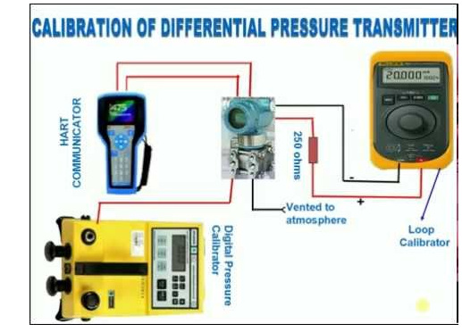
Transmitter calibration requires meticulous preparation. In the preceding post, we have discussed basic setups for calibrating a pressure transmitter. Here we will discuss how to proceed with pressure transmitter calibration.
Steps to Calibrate a Pressure Transmitter
After completing all the preliminary requirements, you can proceed in the following ways:
- Calibrate the 0%, Lower Range Value (LRV) of the transmitter to the LRV of the calibration range. Calibrate the transmitters span to 100%, Upper Range Value (URV) of the calibration range. For example: If you are using Differential Pressure transmitter with power output 4-20mA to measure pressure in the range 0-300 PSIG, then the transmitter’s 0% LRV is 4mA, and is calibrated to 0PSIG. Similarly, the 100% URV is 20mA, and will be calibrated to 20 mA.
- Locate the ZERO and SPAN/RANGE screws of the transmitter by referring the instruction manual. These screws are each connected to the potentiometer and can be turned easily.
The potentiometer allows up to 20 turns between the maximum and minimum resistance. This means 20 clockwise or anticlockwise turns of ZERO and SPAN screw will cause the potentiometer to be at maximum or minimum. In many brands of DP transmitters, the ZERO and RANGE adjustments are interconnected. This means adjusting one screw may affect the other.
- Turn the RANGE and ZERO screws clockwise 20 times. Next, turn the screws 10 times in the counter clockwise direction to adjust the potentiometer between the maximum and minimum resistance. This step is performed to set the mid resistance point at 50%.
- Apply the LRV 0% on the high side of the transmitter, and low vented side. This helps diminish the differential pressure across the DP cell of the transmitter.
- Adjust the ZERO screw on the transmitter by observing the 4mA indication in the current meter. This is the LRV output of your transmitter. At times, this value may not be 4 mA, but you should get a value closer to that.
- Next, apply pressure on the high side of the transmitter to increase the value to the 100% higher value (URV) of the calibration range.
- Adjust the RANGE Screw by observing the meter’s current indication, which should show 20 mA, which is the 100% URV output of the transmitter.
- In ideal situation, 100% of the transmitters input should correspond to the set standard readings of transmitters 100% output (4-20 mA). Accurately calibrated pressure is the one, where the values of input equals to the output for all values between 0-100percent.
The pressure transmitter calibration is complete if you find that input and output values are same as expected. If you are not satisfied with the results, you should continue fine tuning the calibration process, until acceptable levels of accuracy is achieved.
The steps mentioned above may differ from the actual steps mentioned in the manufacturer’s guide, however they will help you understand the procedure.
Related Posts
- What are the Steps Involved in Calibrating Pressure Gauge?
- All Important Questions on Reconditioned Transmitters Answered
- Is Remanufactured Transmitter a Better Option than a New One?
- Differential Pressure Transmitters: How Do They Help in Flow Measurements?
- 3 Whats that Explain How Often You Should Calibrate Pressure Transducer
- Guidelines for Troubleshooting Pressure Transducers
- Learn How to Calibrate a Pressure Transmitter – II
- Learn How to Calibrate a Pressure Transmitter
- Know Three Interesting Uses of Pressure Transmitters
- Things to Check before Buying a New Pressure Transmitter
- A Look at Various Types of Industrial Transmitters – Part II
- A Look at Various Types of Industrial Transmitters Part I
- All Questions on Smart Transmitters and their Calibration Answered
- 3 Major Pressure Transmitter Technologies That Made the Device Popular
- An Unconventional Guide to Selecting the Right Pressure Sensor
- Factors To Be Considered While Differentiating $40 and $400 Pressure Transmitters
- Tips to Augment the Performance and Service Life of Pressure Transmitter
- Factors of Consideration When Choosing Pressure Transmitters
- 5 Most Popular Pressure Transmitter Technologies
- Tips to Improve the Performance of Pressure Sensors
- Factors to Consider When Choosing a Pressure Transmitter Manifold
- Safety Tips for Differential Pressure Transmitter Operation
- Impact of Shock and Vibration on Pressure Transducer
- Rosemount 3051S vs 3051C Transmitter – What is Your Choice?
- Rosemount 2088 Vs Rosemount 3051 – A Few Points of Differences Discussed
- Difference in Conventional Transmitters and Smart Transmitters
- How to Choose Diaphragm Seals for Your Application?
- How to Select Pressure Transmitter for Your Application?
- Remote Seals: Significance, Working Principle & Applications
- How Do You Calibrate A Flow Transmitter?
- What is Absolute Pressure Transmitter & how does it work?
- HART Communication Protocol: Overview, Working Principle, Benefits in Industrial Automation
- Absolute and Gauge Pressure Transmitters - Overview and Working Principle
- Flow Meter vs Flow Transmitter: Know the Difference
- How Do You Test for 4 to 20mA Signal in a Pressure Transmitter?
- Multivariable Transmitter: What Is It and How Does It Work?
- Pressure Transmitters vs. Pressure Transducers: Learn the Differential Characteristics
- Procedure to Calculate Accuracy of Pressure Transmitter Discussed
- Testing Pressure Gauges: Processes of Verification Test and Functional Test
- An Ultimate Selection Guide for Flow Transmitters
- The Benefits and Challenges of HVAC System Balancing
- Fluid Flow Isolation Techniques for Pressure Instrumentation
- Understanding Pressure Ranges and Units for Fluid System Monitoring
- Understanding the Impact of Pressure Fluctuations on Drying Performance
- Monitoring and Controlling Energy Production in Power Plants
- Common Challenges in Air Flow Measurement and How to Overcome Them
- Pressure Monitoring in Pump Systems: A Comprehensive Guide
- Exploring Density and Viscosity Measurement in Industrial Processes
- Pneumatic Pressure Controllers: A Safe Choice for Hazardous Areas
- A Practical Guide to Vacuum Measurement and Operation
- Key Sensors for Monitoring Emissions in Wet and Dry Scrubber Systems
- Complete Hydrogen Gas Safety and Measurement Solutions
- Steam Boiler Drum Level Measurement A Comparison of Control System Technologies
- Furnace Flame Sensor Faults Everything You Need to Know for Safe Operation
- Comparison between Multi Valve Manifolds Block Valves and Bleed Valves
- Furnace Flame Sensor Faults Everything You Need to Know for Safe Operation
- Pneumatic Pressure Controllers: A Safe Choice for Hazardous Areas
- How Can Greenhouse Gas Emissions Be Reduced?
- A Practical Guide to Vacuum Measurement and Operation
- Understanding Electrochemical Detection: Principles, Techniques and Environmental Application
QUICK ENQUIRY