Guidelines for Troubleshooting Pressure Transducers
Brian Craig
May 04, 2017
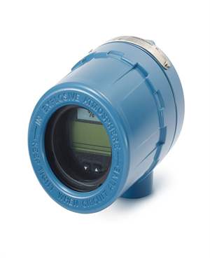
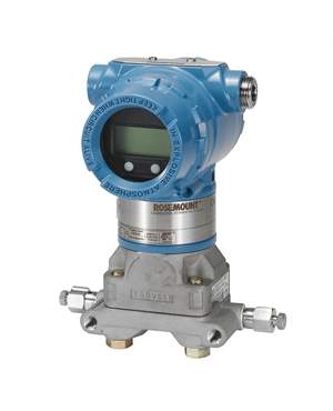
Pressure transducers, also known as pressure transmitters or pressure sensors, are used to convert pressure into analog electrical signals. Stain gages are bonded into the diaphragm of the transducer. The gages are wired into a Wheatstone bridge configuration. The deformation of strain gages converts pressure into an electrical signal, which is used to drive further process. Nowadays, pressure transducers are made from stainless steel, which makes them even more sturdy and reliable. This helps them withstand unfavorable conditions, such as vibration, humidity, or extreme temperature. In spite of this, sometimes it does happen that the installation fails. The pressure transducers failure causes due to issues such as multiple grounds, short circuits, improper wiring, inadequate power supply, incorrect polarity, system operation issues, and so on. This post will focus on some pressure transducer troubleshooting guidelines to help you keep a check on transducer failure.
Troubleshooting Guidelines for Pressure Transducers
The following troubleshooting guidelines will help you ensure that the pressure transducers are operational: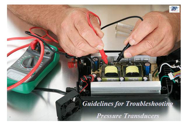
- Basic Understanding about the Pressure Transducer: The basic requirement of troubleshooting a pressure transducer is that the person doing it should have sound knowledge about the equipment. The person should be able to use digital multimeters for measuring resistance, current, and voltage. Also, not to forget, the person doing the troubleshooting should have access to a 24 VDC power source.
- 2-Wire Transducer Connected to a Pipeline: The first thing is to ensure that the -24 VDC is connected to the common, while the +24 VDC is connected to the +excitation of the transducer. Now, disconnect the wire connecting control circuit to the transducer’s +signal. Place – lead of the voltmeter on the common, and the + lead on the + signal of the transducer. Does the transmitter give a voltage output as mentioned in the data sheet? If the answer is yes, then the transmitter is operational.
- 2-Wire Transducer Removed from a Pipeline: The most common problem with the 3-wire pressure transducer is either no or unexpected signal. To tackle this, remove the transmitter from the control unit and pipeline. Check and identify all the terminals, with the help of operating instructions of the model. Now, power the unit and place the + lead of the voltmeter on the + signal of the transmitter, and – lead of the voltmeter on the common. If the transmitter shows the expected reading, then it is working fine.
- 4-20mA Transducer: Ensure that the pressure transducer is connected to the control unit and pipeline. Now, connect the 24 VDC to the red wire of the transducer. Remove the wire of the transducer that is connected to the control unit. The lead going to the control circuit should now be connected to the – lead of the digital milliamp meter. Connect the + lead of the digital milliamp meter to the black wire. Observe the output signal. Does the transducer provide a 4mA output signal, without applying pressure? If yes, then the transducer is operating fine.
When you follow all the guidelines for troubleshooting explained in this and the previous post, it will make your job easier to ensure the proper working of the pressure transducer. You can take help of the experts in the field such as The Transmitter Shop, who have a decent experience in fulfilling instrumentation requirements.
Related Posts
- What are the Steps Involved in Calibrating Pressure Gauge?
- All Important Questions on Reconditioned Transmitters Answered
- Is Remanufactured Transmitter a Better Option than a New One?
- Differential Pressure Transmitters: How Do They Help in Flow Measurements?
- 3 Whats that Explain How Often You Should Calibrate Pressure Transducer
- Guidelines for Troubleshooting Pressure Transducers
- Learn How to Calibrate a Pressure Transmitter – II
- Learn How to Calibrate a Pressure Transmitter
- Know Three Interesting Uses of Pressure Transmitters
- Things to Check before Buying a New Pressure Transmitter
- A Look at Various Types of Industrial Transmitters – Part II
- A Look at Various Types of Industrial Transmitters Part I
- All Questions on Smart Transmitters and their Calibration Answered
- 3 Major Pressure Transmitter Technologies That Made the Device Popular
- An Unconventional Guide to Selecting the Right Pressure Sensor
- Factors To Be Considered While Differentiating $40 and $400 Pressure Transmitters
- Tips to Augment the Performance and Service Life of Pressure Transmitter
- Factors of Consideration When Choosing Pressure Transmitters
- 5 Most Popular Pressure Transmitter Technologies
- Tips to Improve the Performance of Pressure Sensors
- Factors to Consider When Choosing a Pressure Transmitter Manifold
- Safety Tips for Differential Pressure Transmitter Operation
- Impact of Shock and Vibration on Pressure Transducer
- Rosemount 3051S vs 3051C Transmitter – What is Your Choice?
- Rosemount 2088 Vs Rosemount 3051 – A Few Points of Differences Discussed
- Difference in Conventional Transmitters and Smart Transmitters
- How to Choose Diaphragm Seals for Your Application?
- How to Select Pressure Transmitter for Your Application?
- Remote Seals: Significance, Working Principle & Applications
- How Do You Calibrate A Flow Transmitter?
- What is Absolute Pressure Transmitter & how does it work?
- HART Communication Protocol: Overview, Working Principle, Benefits in Industrial Automation
- Absolute and Gauge Pressure Transmitters - Overview and Working Principle
- Flow Meter vs Flow Transmitter: Know the Difference
- How Do You Test for 4 to 20mA Signal in a Pressure Transmitter?
- Multivariable Transmitter: What Is It and How Does It Work?
- Pressure Transmitters vs. Pressure Transducers: Learn the Differential Characteristics
- Procedure to Calculate Accuracy of Pressure Transmitter Discussed
- Testing Pressure Gauges: Processes of Verification Test and Functional Test
- An Ultimate Selection Guide for Flow Transmitters
- The Benefits and Challenges of HVAC System Balancing
- Fluid Flow Isolation Techniques for Pressure Instrumentation
- Understanding Pressure Ranges and Units for Fluid System Monitoring
- Understanding the Impact of Pressure Fluctuations on Drying Performance
- Monitoring and Controlling Energy Production in Power Plants
- Common Challenges in Air Flow Measurement and How to Overcome Them
- Pressure Monitoring in Pump Systems: A Comprehensive Guide
- Exploring Density and Viscosity Measurement in Industrial Processes
- Pneumatic Pressure Controllers: A Safe Choice for Hazardous Areas
- A Practical Guide to Vacuum Measurement and Operation
- Key Sensors for Monitoring Emissions in Wet and Dry Scrubber Systems
- Complete Hydrogen Gas Safety and Measurement Solutions
- Steam Boiler Drum Level Measurement A Comparison of Control System Technologies
- Furnace Flame Sensor Faults Everything You Need to Know for Safe Operation
- Comparison between Multi Valve Manifolds Block Valves and Bleed Valves
- Furnace Flame Sensor Faults Everything You Need to Know for Safe Operation
- Pneumatic Pressure Controllers: A Safe Choice for Hazardous Areas
- How Can Greenhouse Gas Emissions Be Reduced?
- A Practical Guide to Vacuum Measurement and Operation
- Understanding Electrochemical Detection: Principles, Techniques and Environmental Application
QUICK ENQUIRY