What is RTD Sensor and How Does it Work?
Brian Craig
August 14, 2020
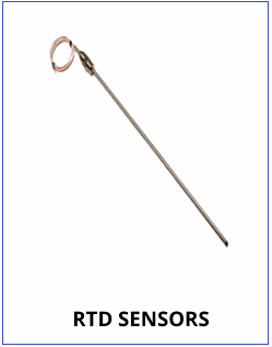
RTD or resistive temperature detector is a probe or a device used to measure and control temperature across industrial applications. A resistor changes its value based on the change on temperature. So, the temperature measurement is relative and not absolute. This relative temperature measurement and control is required across industries where even slight temperature changes impact the process. RTD sensors are known to be accurate in their readings and designed for stability in harsh environments. This means they are resistant to extreme temperatures, vibration, shock, and so on. This post discusses the details about RTD sensors, their working, and more.
What are RTD Temperature Sensors Made of?
This resistive temperature sensor has a coil made from fine wire which is wrapped around a glass or ceramic core and wire wound by RTD elements. This fine wire element is made of platinum as this metal can resist harsh environments, corrosion, and oxidation. At times, copper or nickel are also used. These RTDs at times have more than wire. However, platinum by far is the best option as it offers many benefits. Here are some of the benefits platinum RTDs offer:
- Platinum is chemically inert
- It offers a stable and almost linear temperature-resistance equation
- Platinum as a metal offer a good enough temperature coefficient which enables RTD to sense quick resistance changes
Generally, 2- and 3-wire RTDs are widely used, and this largely depends upon the cabling; RTDs usually has two, three, or four wires. The 2-wire RTDs are commonly used in non-critical applications, wherein the temperature change does not affect the process or only an approximate value of the temperature change is required. On the other hand, 3-wire RTDs find plenty of application in industries. The accuracy of an RTD depends upon the number of wires to some extent. If the number of wires are more, the RTD offers better accuracy. Various configurations of RTDs are available depending upon the either temperature or resistance values, and this can be customized to suit specific industrial applications.
Structural Elements of RTD Sensor
Any RTD comprises five major components as part of its structure. Here are the details:
- Resistance element: This is the temperature sensing element, and in most cases, it is platinum.
- Wires: As mentioned, 2, 3, or 4 wire RTDs are available. These wires are insulated for protection with either Teflon of fiberglass.
- Tubing Materials: Usually for industrial assemblies, Inconel or 316 stainless steel is used for tubes.
- Connection fittings: These include the standard fittings for thermocouple such as welded or compressed fittings.
- Outer diameter of RTD: This is about 6tmm, and is just above the resistance element.
- Cold End Termination: The RTDs can terminate the connection on the cold end with plugs or bare wires.
How does a RTD Sensor work?
When a low amount of current is passed through the element, voltage, which is proportional to the resistance, is measured and converted to temperature calibration units. The temperature is directly proportional to the resistance of RTD. This means when the temperature rises, the resistance of RTD also rises and vice versa. This shift in the temperature is sensed by the detector and accordingly a message is issued to the system. This is the working principle of RTDs- the flow of electricity is resisted with the rise in temperature which is sensed by the resistive element. This resistance is due the metal, and is measured in Ohms. Depending upon the application requirement and the type of RTD, it’s response time may be as fast as 0.5 seconds.
Whether you looking for any temperature measurement devices or specifically RTD sensors, ensure you source them from reliable suppliers. The Transmitter Shop(TTS) has a huge inventory of ready-to-ship temperature measurement devices and related accessories made by recognized manufacturers. The company provides calibration services using SI-traceable units.
Related Posts
- Important Calibration Tips for Pressure Sensors
- What is RTD Sensor and How Does it Work?
- What is a Thermocouple and How Does It Work?
- Why Platinum is a Preferred Choice in RTD Sensors?
- How to Choose the Right Exhaust Gas Temperature Sensor for Your Engine
- Role of Sensors in the Food Processing Plant
- How Can Greenhouse Gas Emissions Be Reduced?
- Understanding Electrochemical Detection: Principles, Techniques and Environmental Application
- Furnace Flame Sensor Faults: Everything You Need to Know for Safe Operation
- Complete Hydrogen Gas Safety and Measurement Solutions
- Complete Hydrogen Gas Safety and Measurement Solutions
- Steam Boiler Drum Level Measurement A Comparison of Control System Technologies
- Furnace Flame Sensor Faults Everything You Need to Know for Safe Operation
- Comparison between Multi Valve Manifolds Block Valves and Bleed Valves
- Pneumatic Pressure Controllers: A Safe Choice for Hazardous Areas
- Furnace Flame Sensor Faults Everything You Need to Know for Safe Operation
- Pneumatic Pressure Controllers: A Safe Choice for Hazardous Areas
- How Can Greenhouse Gas Emissions Be Reduced?
- A Practical Guide to Vacuum Measurement and Operation
- Understanding Electrochemical Detection: Principles, Techniques and Environmental Application
QUICK ENQUIRY