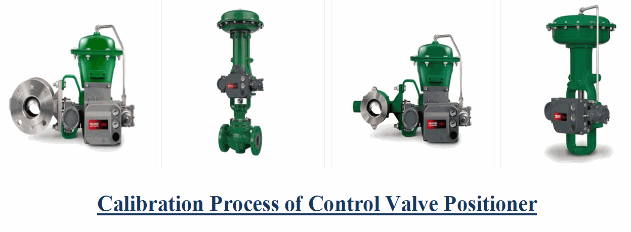
Calibration of Control Valve Positioner: The Process Discussed
Brian Craig
November 23, 2020
Control valves are the devices that monitor and control the process parameters like fluid flow, pressure, etc. The function of control valves relies on a component called the positioner. Although the open/close operation of a control valve can be done using a controller, its position cannot be confirmed without a positioner. In order to offer accuracy to the control valve’s operation, the position of the control valve must be accurate. The position of the control valve is controlled by the positioner. The positioner senses the position of the control valve via a feedback mechanism. The calibration of the control valve positioner is a crucial process and must be done properly for the desired results. Do you know how to calibrate the control valve positioner? If not, then the post leads you through the important steps of control valve positioner calibration and more.
Construction of a Positioner Assembly
Before going into the calibration process, it is important to understand the design of a positioner assembly. The following pointers will help you understand it better.
- The positioner assembly of a control valve consists of a flapper-nozzle, cam linkage, summing beam, and spring and a diaphragm interlinked together with the help of mechanical linkages.
- The summing beam is connected between the cam-spring linkage and the bellow.
- The action of cam-spring is directed by the pressure applied by the flapper-nozzle, which eventually triggers the motion of the summing beam.
- The diaphragm displays the applied and exerting pressure on/by the flapper assembly.
Why Precise Calibration Is Crucial?
A poorly calibrated control valve positioner can result in inefficient process control, increased wear, and higher operational costs. Precise calibration ensures:
- Accurate flow control and process regulation
- Reduced system downtime
- Compliance with industry standards
- Prolonged equipment life
An Overview of Step-by-Step Calibration of Control Valve Positioner
The positioner is responsible for the movement of the flapper. The summing beam is directed in the reverse or forward motion, which acts as the feedback mechanism to the positioner. Since the positioner and feedback mechanisms are assembled in a complete loop, there are two parts of the calibration process of a positioner, namely, zero adjustments, and span adjustments. Let us discuss the steps involved in the calibration process.
Zero Adjustments:
The zero adjustment is done by adjusting the nozzle pin. The following steps are involved in zero adjustments.
- The measurable pressure range is shown on the supply gauge. Move the flapper assembly to the mid-level of the force beam on the forward movement side.
- Set the input value to the lowest reading value.
- Further slowly adjust the nozzle pin to get zero value.
- Then slowly increase the input pressure value to 3psi, and check if you get zero output. If yes, then the zero is adjusted precisely.
Span Adjustments:
The span adjustment is done by moving the flapper assembly to a specific level. The following steps are involved in span adjustments.
- Increase the input pressure slowly till it reaches the maximum pressure value. The input pressure value to the positioner is commonly 15 psi.
- At 15 psi input, check for the maximum output of 20 psi.
- To adjust the span, adjust the flapper assembly by moving the force beam. Ensure that the zero adjustments are made so that the force beam remains at the mid-level only.
- Move the flapper assembly to the lower value if the saturated output value is in the minimum measurable range. Move the flapper assembly to the higher value if the output value is saturated to the maximum measurable range.
This completes the calibration process for a positioner of the control valve. However, the calibration of the positioner has to be precise, therefore, it is essential that it is performed by experts. Thus, you must partner with experienced calibration services like The Transmitter Shop. The company offers calibration and maintenance services. Also, you can buy the control valves from various trusted suppliers to ensure the quality and function of these products.
Trust the Experts for Calibration Valve Services
Given the complexity and precision required, it's highly recommended to trust professionals for your positioner valve calibration needs. At The Transmitter Shop, our experienced technicians follow industry-standard procedures and provide certified control valve calibration services. We also supply quality-tested, refurbished, and new surplus instrumentation from top brands—helping you maintain peak operational efficiency.
Frequently Asked Questions (FAQ):
What is control valve calibration?
Control valve calibration is the process of adjusting a valve and its positioner so that the valve's actual position corresponds accurately with the control signal it receives.
How often should a control valve be calibrated?
Control valves should typically be calibrated annually or during scheduled maintenance, though high-usage systems may require more frequent checks.
What is a positioner in a control valve?
A positioner is a device mounted on the valve that ensures it opens or closes to the correct position based on the control signal. It improves response time, accuracy, and repeatability.
What is calibration in a control system?
In control systems, calibration refers to adjusting instruments or devices so their output aligns with a known standard or input range, ensuring accuracy and consistency in process control.
Why is control calibration important in industrial applications?
Control calibration ensures optimal system performance, prevents process variability, reduces downtime, and extends the service life of equipments.
Related Posts
- Causes & Solutions of Annoying Noise from Control Valves
- Understanding Industrial Control Valves and their Types
- All Important Questions on Control Valves Answered
- 3 Common Control Valve Maintenance Practices
- Know Everything About the Benefits, Applications, Types, and Automation of Control Valves
- How to Select the Right Control Valve for Your Process?
- Calibration of Control Valve Positioner: The Process Discussed
- Control Valve Actuators: Different Types and Failure Modes Discussed
- Calibration Guide for Fisher 3582 Pneumatic Positioner
- How to Do the Periodical Inspection and Maintenance of the Control Valve?
- Temperature Control Valve – Definition and Working Principle
- Reasons to Choose Remanufactured Instrumentation and Control Valves
- Single Acting vs. Double Acting Positioners: Pros and Cons
- Complete Hydrogen Gas Safety and Measurement Solutions
- Steam Boiler Drum Level Measurement A Comparison of Control System Technologies
- Furnace Flame Sensor Faults Everything You Need to Know for Safe Operation
- Comparison between Multi Valve Manifolds Block Valves and Bleed Valves
- Pneumatic Pressure Controllers: A Safe Choice for Hazardous Areas
- Furnace Flame Sensor Faults Everything You Need to Know for Safe Operation
- Pneumatic Pressure Controllers: A Safe Choice for Hazardous Areas
- How Can Greenhouse Gas Emissions Be Reduced?
- A Practical Guide to Vacuum Measurement and Operation
- Understanding Electrochemical Detection: Principles, Techniques and Environmental Application
QUICK ENQUIRY