BLOG
How Do You Calibrate A Flow Transmitter?
Brian Craig
June 25, 2020
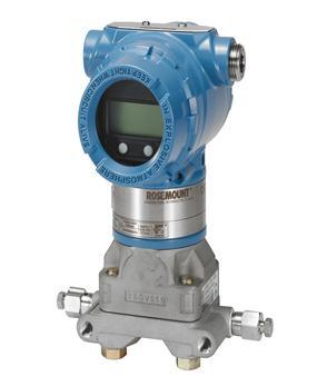
In industrial and domestic applications, substances like gases, liquid, or steam are distributed through pipelines. The properties of fluid largely differ and this affects their flow rate too. Flow meters and flow transmitters are used across industries to measure the flow of gas, as well as liquids in a pipeline. The flow transmitters are basically an advanced version of flow meters. Flow meters can only check the fluid flow, whereas, the flow transmitters can detect flow input and output to control the fluid flow. These flow transmitters are fitted with electronic circuits, which produce an electric signal in the range of 4 to 20 mA or 1 to 5V. Both devices need calibration during installation and also during utilization. There are several manufactures that offer quality flow transmitters like Rosemount flow transmitters, Foxboro flow transmitters, etc. Each transmitter is calibrated differently. However, the basic steps of the calibration process remain the same. This post introduces different processes of flow transmitter calibration.
Process of Flow Transmitter Calibration According to the Type of Transmitter
There are three main types of flow transmitters used today and they are differential pressure transmitters, magnetic flow transmitters, and vortex flow transmitters. These three types require little complex calibration, which is performed using a master meter.
The master meter is a standard calibrated transmitter which performs at optimum conditions and specifications. This device is used as a comparison point for an operating transmitter calibration. The master meter used for the purpose must be calibrated to some international or national standard. Also, it must possess compatibility with the fluid under test.
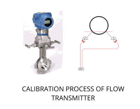
Calibration of Differential Pressure Transmitter:
Although the name suggests a differential pressure transmitter, the measurement is performed based on flow fluctuation itself. Therefore, these differential pressure (DP) transmitters are used for flow measurement as well.
Note: The flow rate is the square root of the pressure drop. Therefore, flow rate readings can be achieved by squaring recorded values of differential pressure.
The calibration process of differential pressure transmitters is as follows.
- Connect the operating DP transmitter and master meter or standard calibrator in series. Run both the transmitters at the same time on the test pipe-line of the same pressure.
- The calibrations are to be performed at five-checkpoints, therefore, mark 5 points by spacers. 10%, 30%, 50%, 70%, and 90% are the points on the spans taken as five checkpoints.
- Take inputs at each point for both standard and operating transmitter devices.
- Compare the readings of both devices at each point. If there is a difference in two readings then that is a correction factor.
- Tune the parameters of operating DP transmitter till you get zero correction factor. Repeat the same procedure for all 5 checkpoints. Once you get all five correction factor values as zero, then the device is fully calibrated. However, hysteresis must be checked because electronic devices may give fluctuating readings for the same checkpoint.
- The output value of the differential pressure will be achieved at each point. Square the values to get a flow rate at each point. Final values of flow rates should match with original manufacturing parameters, mentioned in the manual. This helps cross-check the final calibration.
Calibration of Magnetic Flow Transmitters:
Magnetic flow transmitters’ use a liquid as a conductor, therefore the potential differs as fluid velocity varies.
- The calibration of the magnetic flow transmitter is done using a standard calibrator which acts as a master meter for calibration.
- It involves a five-point check calibration.
- Calculate the input signal. The values required are mentioned on the device.
- o Input Signal= Upper Range x Calibration Factor x Phase band factor.
- Record output values at 5 different test points and then calculate deviation and accuracy.
- Deviation= Theoretical Value- Actual Value.
- o Accuracy= (deviation/Span) x 100.
- Compare the accuracy with the manufacturer’s specifications and adjust the reading until you get zero deviation.
Calibration of Vortex Flow Transmitters:
The vortex flow transmitter functions according to vertex shedding frequency. In this calibration, the input pulse signal and output vertex flow frequency are compared with a calibrator. The calibrator here works as a master calibrator. To perform vortex flow calibration, the following steps are to be followed.
Calculate Vortex Shedding Frequency:
- Vortex Shedding Frequency= Reference factor x Conversion Factor x (Upper range value in US gallons/ Time)
- Vortex shedding frequency is presented in pulse per second (PPS) and the values of RF, CF, URV, are mentioned on the device manual.
After calculation of vortex shedding frequency, set the span jumpers at 5 checkpoints. Connect a frequency generator at the input terminal of the transmitter. Connect the output of the calibrator in series with the transmitter.
Further, set the fine span and make adjustments in the following steps.
- Set frequency generator at upper range value, and adjust fine span screw till you reach 100% value. Then adjust zero on the output value.
- Disconnect the frequency generator and connect the signal lead. Then adjust zero to lower range value.
- Adjust zero, till input and output matches.
- Perform this process for each of 5 checkpoints to complete the calibration.
When working with Rosemount flow transmitter, Foxboro flow meters, etc, the calibration process must be performed according to the manufacturer’s guidelines.
It is important to get the calibration of flow meters done by the experts. Therefore, you must partner with companies like The Transmitter Shop for the calibration. This company has been providing factory new, surplus, and reconditioned transmitters from Rosemount and Foxboro. The company also provides services related to flow, temperature, and pressure measurement services.
Related Posts
Pressure Monitoring in Pump Systems: A Comprehensive Guide
Common Challenges in Air Flow Measurement and How to Overcome Them
Monitoring and Controlling Energy Production in Power Plants
Understanding the Impact of Pressure Fluctuations on Drying Performance
Understanding Pressure Ranges and Units for Fluid System Monitoring
The Benefits and Challenges of HVAC System Balancing
An Ultimate Selection Guide for Flow Transmitters
Procedure to Calculate Accuracy of Pressure Transmitter Discussed
Pressure Transmitters vs. Pressure Transducers: Learn the Differential Characteristics
Multivariable Transmitter: What Is It and How Does It Work?
How Do You Test for 4 to 20mA Signal in a Pressure Transmitter?
Temperature Transmitter: How to Select The Efficient One for Your Application?
Flow Meter vs Flow Transmitter: Know the Difference
Absolute and Gauge Pressure Transmitters - Overview and Working Principle
HART Communication Protocol: Overview, Working Principle, Benefits in Industrial Automation
What is Absolute Pressure Transmitter & how does it work?
Remote Seals: Significance, Working Principle & Applications
How to Select Pressure Transmitter for Your Application?
How to Choose Diaphragm Seals for Your Application?
Difference in Conventional Transmitters and Smart Transmitters
What Are Diaphragm Seals and Their Types?
Rosemount 2088 Vs Rosemount 3051 – A Few Points of Differences Discussed
Rosemount 3051S vs 3051C Transmitter – What is Your Choice?
Impact of Shock and Vibration on Pressure Transducer
Safety Tips for Differential Pressure Transmitter Operation
Factors to Consider When Choosing a Pressure Transmitter Manifold
Tips to Improve the Performance of Pressure Sensors
Important Calibration Tips for Pressure Sensors
5 Most Popular Pressure Transmitter Technologies
Factors of Consideration When Choosing Pressure Transmitters
Tips to Augment the Performance and Service Life of Pressure Transmitter
Factors To Be Considered While Differentiating $40 and $400 Pressure Transmitters
An Unconventional Guide to Selecting the Right Pressure Sensor
3 Major Pressure Transmitter Technologies That Made the Device Popular
The Features and Benefits of Rosemount 1199 Direct Mount Transmitters
What are the Steps Involved in Calibrating Pressure Gauge?
All Important Questions on Reconditioned Transmitters Answered
Is Remanufactured Transmitter a Better Option than a New One?
Differential Pressure Transmitters: How Do They Help in Flow Measurements?
3 Whats that Explain How Often You Should Calibrate Pressure Transducer
Guidelines for Troubleshooting Pressure Transducers
Learn How to Calibrate a Pressure Transmitter – II
Learn How to Calibrate a Pressure Transmitter
Know Three Interesting Uses of Pressure Transmitters