BLOG
How Do You Test for 4 to 20mA Signal in a Pressure Transmitter?
Brian Craig
February 26, 2021
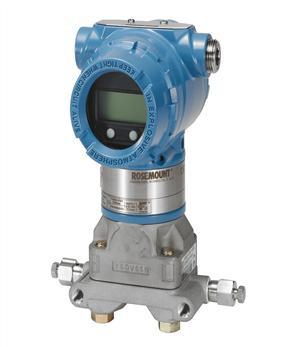
A 4-20mA current loop output or signal is a standard scale of testing and troubleshooting the industrial process control or monitoring devices like pressure transmitters, flowmeters, etc. The modern process parameter control instruments like Rosemount pressure transmitter work on highway addressable remote transducer i.e.; HART protocol. The circuit includes an electronic 2-wire system with 4-20mA current loop output. This scale is essential in examining the performance abilities of the pressure transmitters. Therefore, the testing and troubleshooting of a 4-20mA signal output must be learned by the operator. This post discusses two ways of testing the 4-20mA current output for a pressure transmitter.
Before getting to the testing methods, let us discuss the significance of the 4-20mA current loop output.
The Importance of 4-20mA Current Loop Output Signal in Pressure Transmitters
The 4-20mA signal is a converted value of output generated by a pressure transmitter. The output of the transmitter is sensed based on HART protocol, however, it is converted into the proportional current in order to display it as a reading. Normally, at the zero-level output, the transmitter displays a 4mA signal output whereas, at the maximum or full-scale output, a 20mA signal is displayed on the reading scale.
Verification of 4-20mA current loop signals is a crucial step in the calibration and troubleshooting of a pressure transmitter. By using this scale, the performance configurations are set by the operators.
There are two methods of measuring 4-20mA current loop output, as discussed further.
Methods of 4-20mA Current Loop Output/Signal Measurement
The following are the two methods of measuring a 4-20mA current loop signal utilized by industrial professionals.
-
A 4-20mA Signal Measurement Using Process Clamp Meter: The following steps are taken in order to measure 4-20mA current loop signals without breaking the two-wire circuit.
- Uncover the transmitter in order to gain access to the two-wire current loop and signal wires.
- Connect the process clamp meter to signal wires.
- Identify the mA output signals at zero value of the process clamp meter. The value of mA output must be in the range of 4mA to 20mA.
- If the reading does not show between 4-20mA, then troubleshooting and calibration are required. If the value lies in the range, the transmitter performance is assured.
-
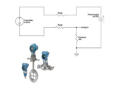
4-20mA Signal Measurement using Loop Calibrator or Multimeter: The 4-20mA signals can be tested by using a multimeter or a loop calibrator by interrupting or breaking the two-wire current loop. The following steps are taken to measure the signal by this method.
- Examine the operation of the pressure transmitter before starting the measurement.
- Uncover the transmitter to reveal the two-wire loop circuit.
- Connect the measuring ends of the two-wire loop with the mA measured. Select the DC measurement function before connecting.
- Disconnect one end of the measuring signal leads, and connect a multimeter or a loop calibrator in series with the transmitter circuit.
- Note the mA reading, which is expected to be between 4mA and 20mA. If the reading is not between the expected ranges then calibration is required.
By using these two techniques, the 4-20mA current loop signals can be tested before troubleshooting or performance analysis of a smart transmitter like Rosemount pressure transmitter.
In order to perform error-free testing of the 4-20mA current signal, it is important to get it done by industry experts. The Transmitter Shop is a company that offers quality pressure transmitters and testing and calibration services too. The company has been offering repair, calibration, and troubleshooting services for new and surplus transmitters for over 30 years. Thus, their experience adds value to the quality of their services.
Related Posts
Pressure Monitoring in Pump Systems: A Comprehensive Guide
Common Challenges in Air Flow Measurement and How to Overcome Them
Monitoring and Controlling Energy Production in Power Plants
Understanding the Impact of Pressure Fluctuations on Drying Performance
Understanding Pressure Ranges and Units for Fluid System Monitoring
The Benefits and Challenges of HVAC System Balancing
An Ultimate Selection Guide for Flow Transmitters
Procedure to Calculate Accuracy of Pressure Transmitter Discussed
Pressure Transmitters vs. Pressure Transducers: Learn the Differential Characteristics
Multivariable Transmitter: What Is It and How Does It Work?
Temperature Transmitter: How to Select The Efficient One for Your Application?
Flow Meter vs Flow Transmitter: Know the Difference
Absolute and Gauge Pressure Transmitters - Overview and Working Principle
HART Communication Protocol: Overview, Working Principle, Benefits in Industrial Automation
What is Absolute Pressure Transmitter & how does it work?
How Do You Calibrate A Flow Transmitter?
Remote Seals: Significance, Working Principle & Applications
How to Select Pressure Transmitter for Your Application?
How to Choose Diaphragm Seals for Your Application?
Difference in Conventional Transmitters and Smart Transmitters
What Are Diaphragm Seals and Their Types?
Rosemount 2088 Vs Rosemount 3051 – A Few Points of Differences Discussed
Rosemount 3051S vs 3051C Transmitter – What is Your Choice?
Impact of Shock and Vibration on Pressure Transducer
Safety Tips for Differential Pressure Transmitter Operation
Factors to Consider When Choosing a Pressure Transmitter Manifold
Tips to Improve the Performance of Pressure Sensors
Important Calibration Tips for Pressure Sensors
5 Most Popular Pressure Transmitter Technologies
Factors of Consideration When Choosing Pressure Transmitters
Tips to Augment the Performance and Service Life of Pressure Transmitter
Factors To Be Considered While Differentiating $40 and $400 Pressure Transmitters
An Unconventional Guide to Selecting the Right Pressure Sensor
3 Major Pressure Transmitter Technologies That Made the Device Popular
The Features and Benefits of Rosemount 1199 Direct Mount Transmitters
What are the Steps Involved in Calibrating Pressure Gauge?
All Important Questions on Reconditioned Transmitters Answered
Is Remanufactured Transmitter a Better Option than a New One?
Differential Pressure Transmitters: How Do They Help in Flow Measurements?
3 Whats that Explain How Often You Should Calibrate Pressure Transducer
Guidelines for Troubleshooting Pressure Transducers
Learn How to Calibrate a Pressure Transmitter – II
Learn How to Calibrate a Pressure Transmitter
Know Three Interesting Uses of Pressure Transmitters