Free Expert Consultation
 Quick Turnaround Shipment
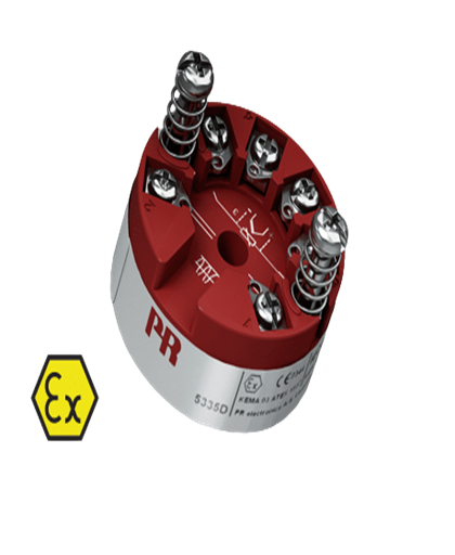
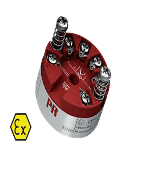
2-Wire Temperature Transmitter with HART Protocol - 5335D
Availability: In stock
Specification
Environmental Conditions:-
Mechanical specifications:-
Common specifications:-
Input specifications:-
Output specifications:-
I.S. / Ex marking:-
Observed authority requirements:-
Approvals:-
- Operating temperature: -40°C to +85°C
- Calibration temperature: 20...28°C
- Relative humidity: <95% RH (non-cond.)
- Protection degree (encl./terminal): IP68 / IP00
Mechanical specifications:-
- Dimensions: Ø 44 x 20.2 mm
- Weight approx: 50 g
- Wire size: 1 x 1.5 mm2 stranded wire
- Screw terminal torque: 0.4 Nm
- Vibration: IEC 60068-2-6
- 2...25 Hz: ±1.6 mm
- 25...100 Hz: ±4 g
Common specifications:-
- Supply:-
- Supply voltage: 8.0...30 VDC
- Isolation voltage
- Isolation voltage, test / working: 1.5 kVAC / 50 VAC
- Response time:-
- Response time (programmable): 1...60 s
- Warm-up time: 30s.
- Start-up time: <2.75 s
- Programming: Loop Link & HART
- Signal / noise ratio: Min. 60 dB
- Accuracy: Better than 0.05% of selected range
- Signal dynamics, input: 22 bit
- Signal dynamics, output: 16 bit
- Effect of supply voltage change: <0.005% of span/VDC
- EMC immunity influence: < ±0.1% of span
- Extended EMC immunity: NAMUR
- NE21, A criterion, burst: <±1% of span
Input specifications:-
- Common input specifications:0
- Max. offset: 50% of selected max. value
- RTD Input:-
- RTD type: Pt100, Ni100, lin. R
- Cable resistance per wire: 5 Ω (up to 50 Ω per wire is possible with reduced measurement accuracy)
- Effect of sensor cable resistance (3-/4-wire): <0.002 Ω / Ω
- Sensor current: Nom. 0.2 mA
- Sensor error detection:Yes
- TC Input:-
- Thermocouple type: B, E, J, K, L, N, R, S, T, U, W3, W5
- Basic accuracy, e.g. TC K: ≤ ±0.25°C
- Cold junction compensation (CJC): <±1.0°C
- Sensor error detection: Yes
- Sensor error current: When detecting / else: Nom. 33 μA / 0 μA
- Voltage input:-
- Measurement range: 800...+800 mV
- Min. measurement range (span): 2.5 mV
- Input resistance: 10 MΩ
Output specifications:-
- Current output:-
- Signal range: 4…20 mA
- Min. signal range: 16 mA
- Load (@ current output): ≤(Vsupply - 8) / 0.023 [Ω]
- Load stability: ≤0.01% of span / 100 Ω
- Sensor error indication: Programmable 3.5…23 mA
- NAMUR NE43 Upscale/Downscale: 23 mA / 3.5 mA
- of span: = of the presently selected range
I.S. / Ex marking:-
- ATEX: II 1 G Ex ia IIC T6...T4 Ga, II 2 D Ex ia IIIC Db, I M1 Ex ia I Ma
- < IECEx: Ex ia IIC T6...T4 Ga, Ex ia IIIC Db, Ex ia I Ma
- FM, US: Cl. I, Div. 1, Gp. A, B, C, D T4/T6; Cl. I Zone 0, AEx ia IIC T4/T6; Cl. 1, Div. 2, Gp. A, B, C, D, T4/T6
- CSA: Cl. I, Div. 1, Gp. A, B, C, D Ex ia IIC, Ga
- INMETRO: Ex ia IIC T6...T4 Ga, Ex ia IIIC Da, Ex ia I Ma
Observed authority requirements:-
- EMC: 2014/30/EU
- ATEX: 2014/34/EU
- RoHS: 2011/65/EU
- EAC: TR-CU 020/2011
- EAC Ex: TR-CU 012/2011
Approvals:-
- ATEX: DEKRA 20ATEX0108X
- IECEx: DEK 20.0063X
- CSA: 1125003
- c FM us: FM17US0013X
- INMETRO: DEKRA 18.0002X
- DNV Marine: TAA0000101
- EAC Ex: RU C-DK.HA65.B.00355/19
- SIL: Hardware assessed for use in SIL applications
Description
Application:-
Technical characteristics:-
Mounting / installation:-
- Linearized temperature measurement with Pt100...Pt1000, Ni100...Ni1000, or TC sensor.
- Difference or average temperature measurement of 2 resistance or TC sensors
- Conversion of linear resistance variation to a standard analog current signal, for instance from valves or Ohmic level sensors
- Amplification of a bipolar mV signal to a standard 4...20 mA current signal.
- Connection of up to 15 transmitters to a digital 2-wire signal with HART communication
Technical characteristics:-
- Within a few seconds the user can program PR5335D to measure temperatures within all ranges defined by the norms.
- The RTD and resistance inputs have cable compensation for 2-, 3- and 4-wire connection.
- The 5335D has been designed according to strict safety requirements and is therefore suitable for application in SIL installations.
- Continuous check of vital stored data for safety reasons
- Sensor error detection according to the guidelines in NAMUR NE89.
Mounting / installation:-
- For DIN form B sensor head mounting
Technical Data-Sheet
 PR ELECTRONICS 5335D-18967-US.pdf