Free Expert Consultation
 Quick Turnaround Shipment
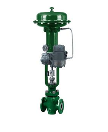
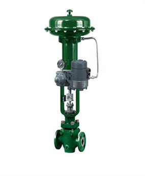
Fisher 846 Electro-Pneumatic Transducer
Availability: In stock
Specification
Input Signal:-
Jumper selectable, ON or OFF, if unit includes option
Reading Off
Reading On
- Standard Performance:
- 4 to 20 mA DC, 4 to 12 mA DC, or 12 to 20 mA DC. Field adjustable split ranging.
- Multirange Performance:
- 4 to 20 mA DC. Consult factory for split range input.
- Standard Performance:
- (Consult factory for split range output)
- Direct Action (Minimum span of 6 psi)
- Typical outputs: 0.2 to 1.0 bar (3 to 15 psi).
- Rangeability between 0.1 and 1.2 bar (1 and 18 psi).
- Reverse Action (Minimum span of 11 psi)
- Typical outputs: 1.0 to 0.2 bar (15 to 3 psi)
- Rangeability between 1.2 and 0.1 bar (18 and 1 psi)
- Multirange Performance:
Direct Action (Minimum span of 6 psi) - Typical outputs: 0.2 to 1.9 bar (3 to 27 psi), 0.4 to
2 bar (6 to 30 psi), and 0.3 to 1.7 bar (5 to 25 psi)
Rangeability between 0.03 and 2.3 bar (0.5 and 33 psi). - Reverse Action (Minimum span of 11 psi)
- Typical outputs: 1.9 to 0.2 bar (27 to 3 psi), 2 to
0.4 bar (30 to 6 psi), and 1.7 to 0.3 bar (25 to 5 psi)
Rangeability between 2.3 and 0.03 bar (33 and 0.5 psi)
- Standard Performance:
- 1.2 to 1.6 bar (18 to 24 psi)
- Multirange Performance:
- 0.2 bar (3 psi)(3) greater than the maximum
calibrated output pressure - Maximum:
- 2.4 bar (35 psi)
- Clean, dry air
- Per ISA Standard 7.0.01:
- A maximum 40 micrometer particle size in the air
system is acceptable. Further filtration down to 5
micrometer particle size is recommended. Lubricant content is not to exceed 1 ppm weight (w/w) or
volume (v/v) basis. Condensation in the air supply
should be minimized - Per ISO 8573-1:
Maximum particle density size: Class 7
Oil content: Class 3
Pressure Dew Point: Class 3 or at least 10°C less than
the lowest ambient temperature expected
- Standard:
- 6.4 m3/hr (240 scfh) at 1.4 bar (20 psi) supply pressure
- Multirange:
- 9.7 m3/hr (360 scfh) at 2.5 bar (35 psig) supply pressure
- 0.3 m3/hr (12 scfh) at 1.4 bar (20 psi) supply pressure
- Operating: -
- -40 to 85 ℃ (-40 to 185 ℉)
- Storage: -
- 40 to 93 ℃ (-40 to 200 ℉)
- 0 to 100% condensing relative humidity
- Note: The performance of all 846 I/Ps is verified
using computer automated manufacturing systems
to ensure that every unit shipped meets its
performance specifications.
Linearity, Hysteresis, and Repeatability: - ±0.3% ofspan.
- Temperature Effect (total effect including zero and
span): - ±0.07%/ ℃ (0.045%/ ℉) of span
- Vibration Effect:
- ±0.3% of span per g during the following conditions:
5 to 15 Hz at 4 mm constant displacement
15 to 150 Hz at 2 g. 150 to 2000 Hz at 1 g.
per SAMA Standard PMC 31.1, Sec. 5.3, Condition 3,
Steady State. - Shock Effect:
- ±0.5% of span, when tested per SAMA Standard PMC 31.1, Sec. 5.4.
- Supply Pressure Effect:
- Negligible
- Electromagnetic Interference (EMI):
- Tested per IEC 61326‐1 (Edition 1.1). Meets emission levels for Class A
equipment (industrial locations) and Class B
equipment (domestic locations). Meets immunity
requirements for industrial locations - Leak Sensitivity(4):
- Less than 1.0% of span for up to
4.8 m3/hr (180 scfh) downstream leakage - Overpressure Effect:
- Less than 0.25% of span for
misapplication of up to 7.0 bar (100 psi) supply
pressure for less than 5 minutes to the input port. - Reverse Polarity Protection:
- No damage occurs from reversal of normal supply
current (4 to 20 mA) or from misapplication of up to
100 mA.
- Supply Air, Output Signal, and Output Gauge:
- 1/4‐18 NPT internal connection
- Electrical:
- 1/2‐14 NPT internal conduit connection
- Zero and Span:
- screwdriver adjustments located in terminal compartment.
Jumper selectable, ON or OFF, if unit includes option
- Frequency Range:
- 0 to 10,000 Hz
- Amplitude:
- : 0.4 to 1.0 Vp‐p
Reading Off
- Min. 6.0 V (at 4 mA)
- Max. 7.2 V (at 20 mA)
Reading On
- Min 6.4 V (at 4 mA)
- Max. 8.2 V (at 20 mA)
- Hazardous area:
- CSA C/US—Intrinsically Safe, Explosion-proof,
Non-Incendive. - FM—Intrinsically Safe, Explosion-proof, Non-Incendive.
- ATEX—Intrinsically Safe, Flameproof, Type n
- IECEx—Intrinsically Safe, Flameproof
- Refer to Hazardous Area Classifications and Special
Instructions for “Safe Use” and Installation in
Hazardous Locations in Section 2 for additional
information
Electrical Housing:
Tropicalization (Fungus test per MIL-STD-810) - CSA C/US—Type 4X
- FM—Type 4X
- ATEX—IP66(6)
- IECEx—IP66(6)
- INMETRO—National Institute of Metrology, Quality,
and Technology (Brazil) - KGS—Korea Gas Safety Corporation (South Korea)
- NEPSI— National Supervision and Inspection Centre
for Explosion Protection and Safety of Instrumentation (China)
- Housing:Low‐copper aluminum with polyurethane
paint, or 316 stainless steel. - O‐Rings:Nitrile, except silicone for sensor O‐rings.
- Fisher 67CFR filter regulator, supply and output
gauges or tire valve remote pressure reading, module
cover with multiple stroke ports, stainless steel
housing, or stainless steel mounting bracket.
- Aluminum: 2.9 kg (6.5 lb) excluding options
- Stainless Steel: 6.7 kg (14.8 lb) excluding options
Description
Fisher® 846
Fisher® 846 electro-pneumatic transducer accepts an electrical input signal and converts it to a pneumatic output signal. The transducer includes a patented deflector/nozzle design that consists of two nozzles positioned so that the constant air flow exiting the supply nozzle. Vibration resistant and tolerant of dirty supply air.
- Vibration Resistant—The low-mass pilot stage, mechanically damped deflector bar, and rugged construction provide stable performance in vibration.
- Large Diameter Nozzles—Large diameter nozzles, free-flow pilot stage design, and large internal pneumatic supply passages provide excellent tolerance to reducing the effects of contaminant buildup and erosion.
- Increased Accuracy, Reduced Sensitivity to Supply Pressure Variations and Downstream Leakage—The electronic feedback control network monitors the pneumatic output signal, detects any input-output deviations and corrects them. This provides very high accuracy and allows the transducer to sense changes in the final element condition and rapidly optimize its air delivery.
Technical Data-Sheet
 Fisher-846-Current-to-Pressure-Transducer.pdf